


DISCLAIMER: I actually know very little about electronics and this is one of my first projects, so please excuse the obviousness of some things I've written (they weren't exactly "obvious" to me when I started). Also, if you find an error in the text or the project please point it out in the comments - thanks! ;>
Two joysticks to one port?
As I've learned on CPCWiki, JY-2 - one of the official Amstrad CPC joystick - had a port in the back to which you could connect a second CPC joystick (sidenote: CPC joysticks are a little different than e.g. Amiga joysticks; while you can use an Amiga joystick with CPC, a CPC joystick might not work with Amiga) and you could use both joysticks as separate devices (joy(0) and joy(1) if we were speaking BASIC). The way this works is actually pretty simple, but let's start with "how a CPC joystick works" just to make sure we're on the same page.A standard 8-bit computer joystick connector is a 9-pin D-SUB and it's the same in this case. One of the pins is called "common" (or just "com") and is set to LOW. The other 7 pins (one is "unused") represent directions ↑ ↓ ← → as well as FIRE 1/2/3, and are connected to "inputs" (set to HIGH by default) of the joystick controller inside the CPC (actually they are connected to the keyboard controller, which, in fact, is the "sound card" chip - but that's a story for a different time).
Now, if you press a button or move the stick in some direction, an "input pin" gets connected to the "common" track, which causes the "input" to go LOW in the controller and so the "internal state" of the joystick in the controller changes to represent the new state.
So, how do you connect two joysticks to a port with 9-pins when one joystick uses 1+7 pins? Well, you make both joysticks use the same 7 "input pins", but different "common" pins (in case of connector at the back of the CPC464 "common 1" is on pin 8 and "common 2" is on pin 9), and you keep only one "common" pin "active" at a time (by "active" I mean "LOW", and by "deactivated" I mean "HIGH") - you basically scan one joystick (by activating it's common pin) and then scan the other (by deactivating the first common pin, and activating the other).
So, the JY-2 just "forwarded" the 7 pins to the back port, and the "common 2" pin to the back port's "common" pin.
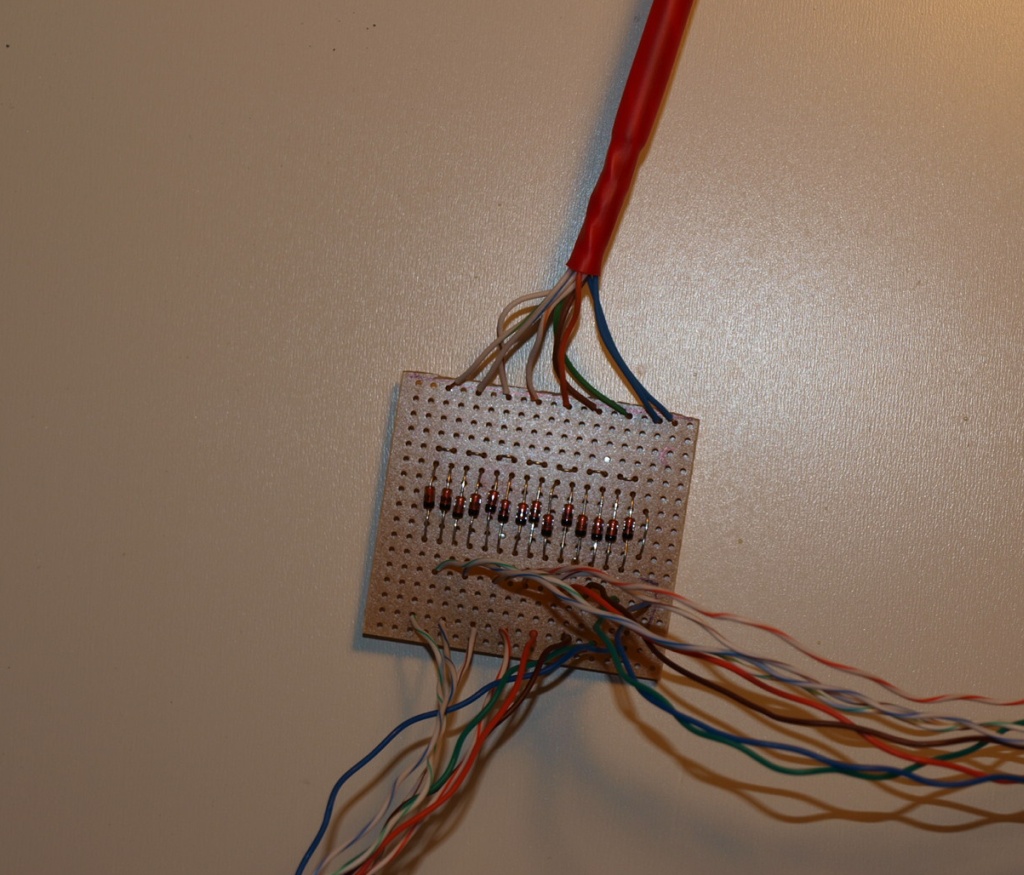
My splitter works exactly the same way, though I added some diodes to get rid of the key ghosting effect.
[A quick note on FIRE 1/2/3 - CPC games used mostly FIRE 1, but as far as I recall FIRE 2 is also officially supported. FIRE 3 however is "undocumented" and it's said it's input is not even connected on some CPC464 models (my CPC has it connected). That being said, the joysticks I have support only FIRE 1, even though they have 2 buttons; the buttons either share the same wires (in case of my black CPC-compatible joystick) or the other button is used for something else - e.g. turning on auto-fire (in case of my Amiga-compatible joystick). Random thought: since there are 14 "signals" total, it's just one "signal" short of connecting three ↑ ↓ ← → + FIRE 1 joysticks without too many hacks, blah ;p]
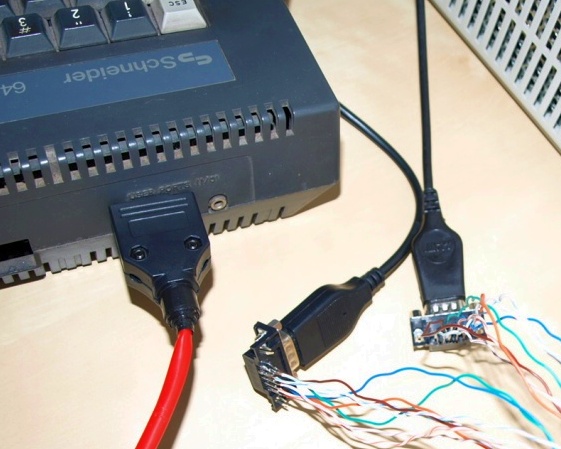
The finished piece
Before I get to the longer description let me show you the finished "CPC464 1-to-2 Joystick Port Splitter". Actually almost finished, since I still have to put it in a nice casing (I'll update the post later).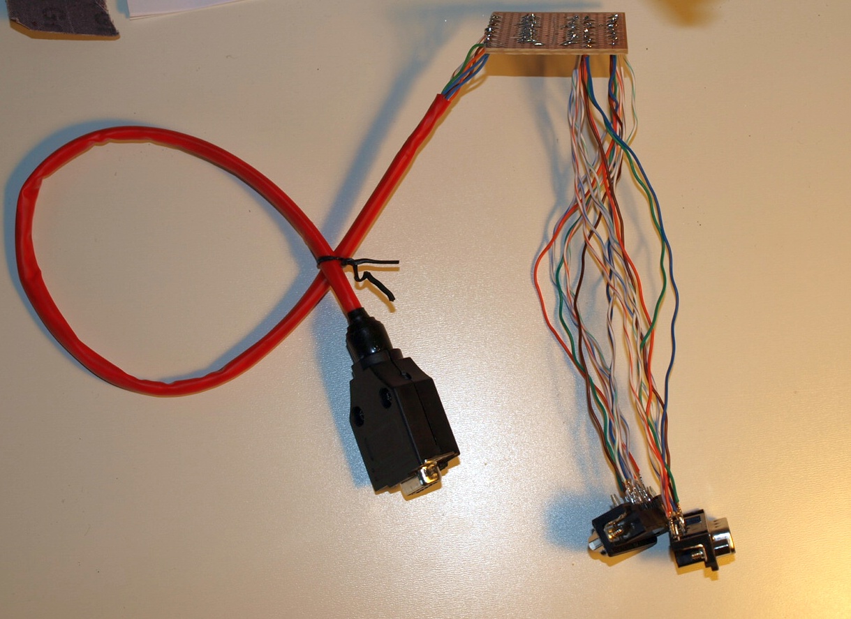

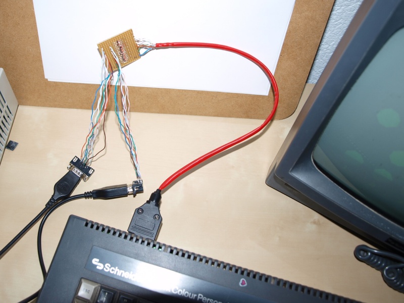

VIDEO: Initial test
VIDEO: Testing for key ghosting
The journey
Even though the project is really simple it took me quite a while to make. There were a couple of reasons for that:- First of all, quite a lot of time was consumed by just getting/waiting for parts (2 * online order + 1 * just going to the local shop).
- Second of all, I wanted to learn as much as possible during this project (so I've done some things that one could just skip).
- And finally, I actually made a mistake due to which I had to start from scratch at one point.
In any case, I decided to document "the journey to the splitter" ;>
As said before, I first learned about the possibility of two-joystick support from CPCWiki (it's a really good site) and I started by reading everything I could find about joysticks there. That would be:
- CPCWiki - Digital Joysticks
- CPCWiki - Amstrad JY-1/JY-2 joysticks
- CPCWiki - Connector:Digital joystick
[Actually now I see there are a lot of references to splitters and "Y-cables" (as they call it) there. Funny. I didn't see them before. Well, I guess that's all for the better anyway, since I've learned more this way.]
Next, I've plugged in a standard D-SUB 9pin extender cable (or so I thought) and started playing with connecting random pins and trying to make a map of what is what... and I found out that the pins are actually different than suggested on CPCWiki (actually, I was wrong; keep reading ;>).
Also, I've got my hands on the schematics of the CPC464 mainboard (surprisingly easy to find on teh internets), and I've started studying them, finding out about how the "scan" works, and that the joystick is connected to the keyboard controller (if you move the joystick, some characters appear on the screen). I won't go into details here, it's a story for another time.
In the meanwhile I started designing the whole "splitter" - in my first design I would use an Arduino controller, but getting deeper I found it totally unnecessarily, so my second design was just cables connecting pins.
However, thinking about it, I found a problem - if you would have one common "state" on both joysticks (e.g. both joysticks would have FIRE 1 pressed), then the rest of the states would "leak" from one joystick to the other. Let's look at the following simplified scenario:
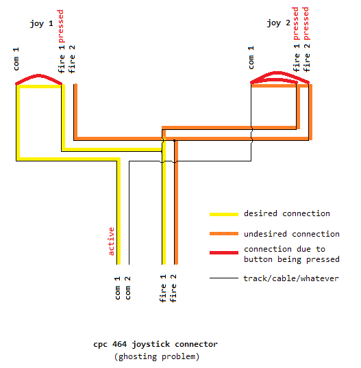
As you can see, since in joystick 1 "common 1" and "fire 1" are connected, and in joystick 2 "common 2", "fire 1" and "fire 2" are connected, that means that indirectly "fire 2" and "common 1" are also connected. Of course, this is not desired.
I figured out, that placing some diodes might solve the problem, though I was a little reluctant to connect diodes without resistors (habit gained from hearing "always use a resistor with a diode" all the time). Also, I was worried that the voltage drop on the diodes might cause the problem. And actually I found out that neither of these problems exists in this case - that being said, I would like to thank lcamtuf for taking some time to assure me that in this case diodes without resistors will not explode (and also pointing out few other interesting details) ;>
As I later found out this problem is called "ghosting" and goes in pair with "masking" (thanks go to Unavowed for the link/name). Anyway, the problem is solved exactly the way I solved it, so I'm pretty happy with myself ;>
[Kinda related: Being curious I've looked in the CPC464 keyboard schematics to check how it's solved there, and... well... it's not; e.g. if you press W R T at the same time, letters W R T E (sic) will appear on the screen]
Now came the time to construct a prototype and test it. So I've soldered a few cables to the D-SUB connectors, connected them on a breadboard, connected the joysticks, and.... nothing happened! It didn't work! Well, I'm pretty used to debugging anyways ;>
I've started by disassembling one of the joysticks (the CPC-compatible) and found that the pins are entirely different than what I had on my "pin map". Why? Do you remember the "D-SUB 9pin extender cable" I mentioned? It turned out not to be an extender cable after all but some kind of a Null modem cable I used for connecting my PCs some time ago. Ugh.
So I was back at the start point. Again, connect a real (and double-checked) extender cable (I actually had to wait a coupled of days for it to arrive, as well as some additional D-SUB connectors) and map the pins again (guess what - they turned out to be exactly the same as stated on CPCWiki... surprise surprise).
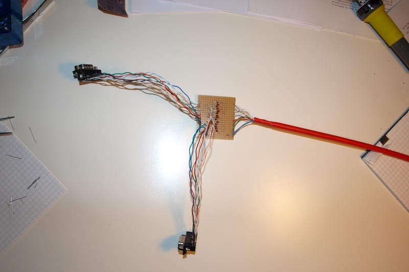
Some time after that I finally got to assembly the final design on a slightly modified universal board (I had to "break" some tracks) and it even worked at the second attempt (obviously I broke one track too many and found out about it in another of the debugging session).
And that's the whole story. I must admit I'm pretty happy with this project since it's my first "extension" for an 8-bit computer and I was able to make it from scratch as well as foresee and solve the ghosting problem, and learn A LOT about both electronics and CPC464 in the process.
Anyway, once I've finished my "splitter" I've looked around for similar projects/info and it seems there are quite a lot of them on the internets:
- CPCWiki - Joystick Y-cables
- CPCWiki - Joystick Splitter
- DIY Joystick Splitter Project (ghosting warning ;>)
Joystick testing software
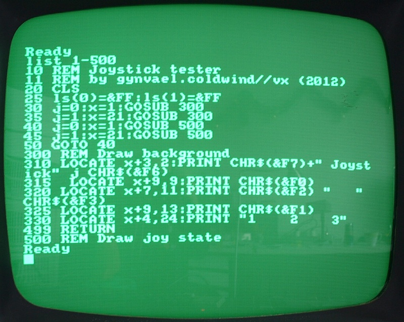
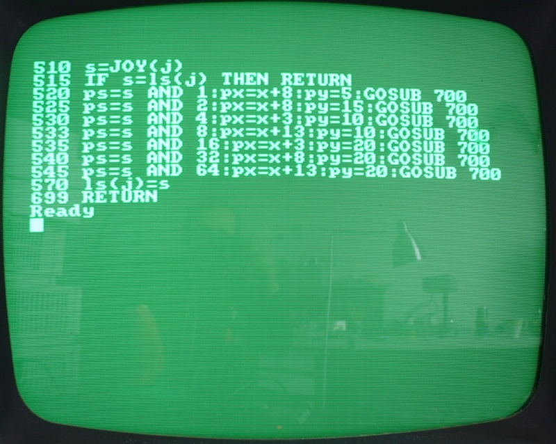
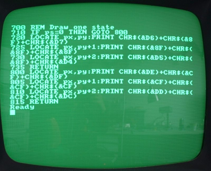
A quick note on the joystick testing software (though "software" is actually a too-big word) you can on the videos/photo above. The program was written in the standard CPC Locomotive BASIC in ~30 minutes (grrr, it's "LOCATE" not "POSITION"... old ATARI BASIC habits die hard), is kinda laggy (it was even "laggier" in the previous version) and unfortunately I have currently no way to transfer the listing to the PC.But... I've made photos of the code so you can take a look in case you're really curious:
And that's it for today.
Comments:
I've seen a ghost on second screenshot! He is ghosting with two joysticks in one and camera in other hand.
ew. podłącz amperomierz i zobacz jaki prąd leci myślę że standardowo 20mA no może - bo starsze to może z 0,1 A ;P
myślę że będzie git z tymi szybkimi diodami, bez dodatkowych rezystorów.
Najlepsze bylyby diody krzemowe (od razu zaczynają przewodzić z prawie liniową charakterystyką narastającą, czyli jak przeciekający zawór działa - dla nas to porządane), i zabijcie ale nie pamiętam czy 1n4007 jest krzemowy a muszę iść kimać :P
Pozdrawiam i gratuluję fajnego wykonania zabawki :)
I made a cable from CPCWiki too and then I made a pcb from that schematic :-/
Don't ask why :-D
http://s26.postimg.org/nk6fcqw7t/IMAGE00020.png
Add a comment: