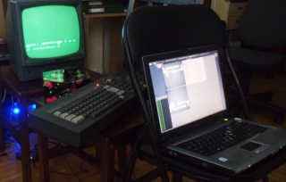
 Waiting for my new programmer (which will arrive "at the end of the week") I decided to dump RAM from my new Amstrad to my PC. But there was a problem - how to do it without having any cables to connect them, without floppies, etc? Well, I found a funny way to do it ;D
Let's start with a brief description of that way. The idea is based on a fact that CPC 464 can display data on the monitor. And a PC can have an "internet" camera plugged into USB. And that camera could read the data from the CPC monitor! Simple, aye?
Well, yes, simple, but a few questions arouse anyway - for example - how should the data be presented? How much data should be shown at once? How fast should the data switch? How to tell the PC that the data did in fact switch? Will Amstrad be fast enough to display the data? Will the camera be "fast" enough to capture all the needed frames? What if the camera catches a frame on which the screen is half-way drawn? Etc...
Let's start from the beginning. The way the data is shown depends strictly on the quality of the camera, and on how much code would we wanna write on the PC. Generally speaking, there are two ideas:
- We show the data as hex strings, and on the PC side we have an OCR (neural networks is a good choice here) that will read the data (letter by letter) - this requires a good quality of the camera, a good resolution, and more code on the PC side,
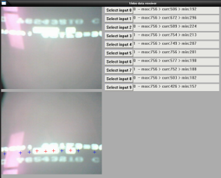
- Or, we could show the data as dots (rectangles, 1 pixel or larger) on the screen, bit by bit, and check on the PC if the dot is lit, or not - the number of data we could send in one frame depends again on the quality of the camera image, and on the resolution of CPC 464, and it requires less code on the PC side.
In my case I've used a simple small "internet" camera, which I had trouble to convince to get a decent quality of image, so the OCR idea was out of the question - I had to use the second idea. I thought it will be OK if I send just 8 bits of data per frame (a small amount, but sufficient for my needs) every half of a second (it's easy to calculate that sending the whole RAM of CPC 464 - 64 kb - will take about 10 hours).
 How to tell the PC that there is a new frame waiting? Ah, the old synchronization problem (see ethernet or USB), which has been solved many many times. In my case, I decided to use another bit as a flag. The change of the flag indicates the change of the data frame (it starts with being lit). So, the flag will be lit on even addresses, and will be dark on odd ones. If the PC monitors this flag, it will know when new data frame is ready.
What about the problem of the frame being caught when the screen is only half-drawn? I've used a very simple trick - I draw the sync flag twice - at the start and at the end of the data. This way if the image frame is caught in the 'wrong' moment, then the sync flags will differ (since the second one will be from the old data frame). And if the sync flags differ, the PC app will throw away this image frame, and wait for another one. My camera takes about 3-5 image frames from each data frame, so it's not a problem if the program throws out a data frame.
When implementing this idea, I stumbled on another problem, related to a CLS (clear screen) called between frames. Sometimes the camera caught a blank screen, and the program figured that it's an new data frame (in case the last data frame had lit sync flags - a blank screen would be interpreted as dark flags), and said that the data is '00000000'. To solve this problem, I decided to store all the data acquired from the start of the data frame, till the end, and then, choose the middle one as the "right" one. Well, later it came to me that the CLS wasn't needed anyway ;D
By the way...
If want to improve your binary file and protocol skills, check out the workshop I'll be running between April and June → Mastering Binary Files and Protocols: The Complete Journey
As for the PC, I've used Windows and WinAPI (I had to update my MinGWs WinAPI headers/libs huh) for the app - mainly I've used the cap* functions (capCreateCaptureWindow, capDriverConnect, etc, all from vfw.h). The application itself was very simple - it was a preview window with stuff for selecting places to look for data. There was some minor trouble with calibrating the app (in my case the best "formula" was to set a data bit to 1 if the pixel color is almost white, and 0 otherwise - where "almost white" was about 8% difference at most), and some minor bugs, but after fixing and resolving it appears to work.
The source code for the PC app can be downloaded here, but I must warn You, the code is weak, ugly, and stupid (since I wanted it to work, not to be miss universe ;D).
The source code for the CPC 464 is still on the CPC 464, and I'll "copy" it as soon as the RAM dump finishes (when I was writing this post on the Polish side of the blog, there was about 8h left, at least I thought so... it looks like it was more, since the app is still running, and it's currently at memory offset &B759).
As for "stuff to fix later", I think it's a good idea to add some data compression - RLE fits here well. There are a lot of "blank" (zeroed) spaces in memory, that use too much time to transfer.
Transmitting more then 8 bits at a time is also a good idea.
Summarizing, the whole setup works just like a plain optic fiber, the medium is air, the transmitter is a monitor instead of a LED, and the receiver is a camera. As for the name (lightsack) - I 've put a blanket on it to protect it from external "noise" (flashes of light, reflections on the screen, etc), and it looks like a giant sack now, a light sack he he he.
And that is all for today.


Comments:
Podsyłam podobny temat i ciekawe rozwiązanie (Atari):
http://atarionline.pl/v01/index.php?subaction=showfull&id=1342989992&archive=&start_from=0&ucat=1,7&ct=nowinki
Pozdrawiam!;)
Add a comment: