


 So my old Atari 800XL broke and I decided to fix it. Well, that's not the whole story though, so I'll start from the beginning: a long time ago I was a proud owner of an Atari 800XL. Time passed and I eventually moved to the PC, and the Atari was lent to distant relatives and stayed with them for several years. About 15 years later I got to play with my wife's old CPC 464 (see these posts: 1 2 3 4 - the second one is probably the most crude way of dumping ROM/RAM you've ever seen) and thought that it would be pretty cool to check out the old 800XL as well. My parents picked it up from the relatives (I currently live in another country) and soon it reunited with me once again! Unfortunately (or actually, fortunately) technological development moved quite rapidly through the last 20 years so I found myself not having a TV I could connect the Atari too. And so I ordered an Atari Monitor → Composite Video cable somewhere and hid the Atari at the bottom of the wardrobe to only get back to it last week.
After connecting 800XL via Composite Video to my TV tuner card (WinFast PxTV1200 (XC2028)) it turned out that the Atari was alive (I actually thought it won't start at all due to old age), it boots correctly, but the video is "flickery":
So I decided to fix it. Now, the problem is I have absolutely no idea about electronic circuitry - my biggest achievement ever in this field was creating a joystick splitter for CPC 464 (though I am actually proud of myself to have predicted the ghosting problem and fixing it before soldering anything). Which means that this whole "I will fix the Atari" statement actually means "I will learn something about electronic circuits and probably break the Atari and it will never ever work again and I will cry" (though I hope to avoid the latter).
This blog post is the first of an unknown number of posts containing my notes of the process of attempting to fix my old computer. To be more precise, in this post I'm actually describing some things I've already did to try to pinpoint the problem (this includes dumping frames directly from GTIA - this was actually fun to do). Spoiler: I still have no idea what's wrong, but at least I know what actually works correctly.
Part 1 - Debugging, some soldering, more debugging
My guess is that fixing electronic equipment is like fixing a nasty bug in unknown code. You need to familiarize yourself with the code in general and then start the process of elimination to finally pinpoint the cause of the problem. After you have done that, you need to understand in depth the problem and the cause. And then you fix it.
So from a high level perspective I expect the problem to be in one of four places:
1. The Atari motherboard itself.
2. The Atari Monitor socket → Composite video cable I'm using.
3. My TV tuner card.
4. The application I'm using for the TV tuner.
Starting from the bottom I first tried VLC to get the image from the tuner - this worked but I still got the same artifacts and I wasn't able to convince VLC to actually use the parameters I'm passing to it (I suspected the tuner is selecting the wrong PAL/NTSC mode). So I switched to CodeTV which actually did allow me to set various PAL and NTSC modes, but it turned out to not to fix my issue - actually after seeing the effect of decoding the signal as e.g. NTSC I decided this has absolutely nothing to do with my problem. So that's one point off the list.
Next was the TV tuner card. My card - WinFast PxTV1200 (XC2028) - is a few years old and I never had much luck with it, so I ordered a new one - WinTV-HVR-1975. It should arrive next week, so whether it fixes anything will be revealed in the next part. I'll also play with some other options once I'm add it.
The second point on the list is the cable, and I'm yet to order a replacement, so I'll update this debugging branch in the next part as well.
Which brings us to the fun part - the motherboard itself.
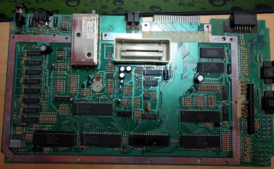
I started by pestering my Dragon Sector teammate and our top electronics specialist - q3k - about what oscilloscope should I buy (I have some limited oscilloscope training and I figured it will be useful) and he recommended RIGOL DS1054 + a saleae logic analyzer (I got the Logic Pro 16 one) + some other useful pieces of equipment for later.
The second thing I did was to desolder all of the old electrolytic capacitors (making quite details notes about where they were and what types they were) as it seems to be a pretty standard thing to do when it comes to old computers. Once that was done (and I was able to read all of the labels, as some were initially hidden, especially in case of the axial ones) I ordered new ones and patiently waited a few days for them to arrive (along with some IC sockets which I plan to use later).
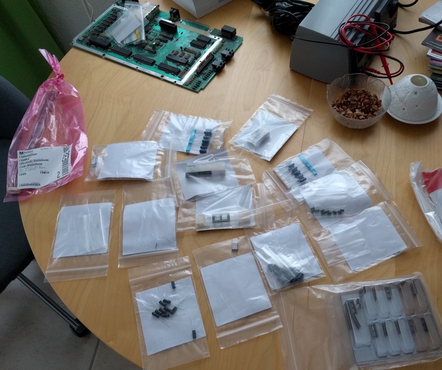
Once they did, I cleaned the motherboard around where they were at and soldered them in (I'm obviously not going to show you a hi-res photo of this as my soldering skills are that of a newbie) and connected the Atari to test it. It did boot, but the video problem was still there.
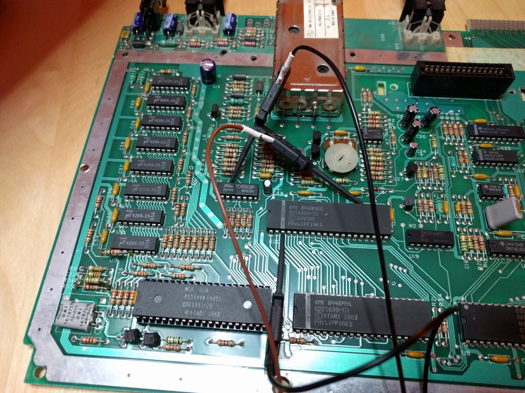
Chatting on IRC a colleague (hi skrzyp!) mentioned that it might be a GTIA problem (Graphic Television Interface Adaptor - the last IC in the line that runs Atari's video) so I decided to dump the video frame right at the moment it leaves GTIA. Researching the topic on the internet I learnt that Luminance Output 3 (i.e. pin 24) actually should be the Composite Video output (or what later becomes Composite Video); I also found out that pin 25 is Composite Sync Output, which meant I had all I needed to start.
Given that I didn't know much about Composite output I started by connecting my oscilloscope to the Composite Sync Output pin in hopes it will tell me something.
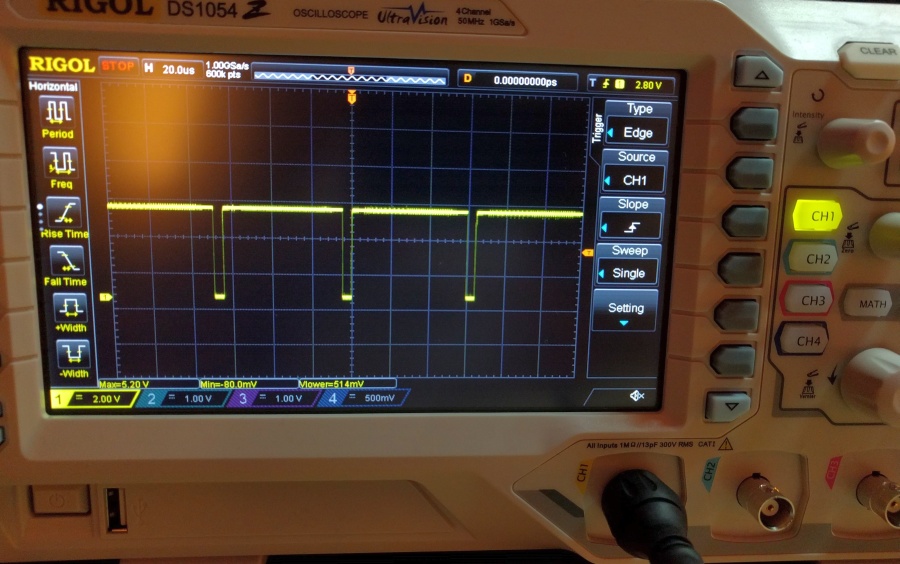
And indeed it did. It seemed that the sync signal is high for about 60μs and then low for about 5μs - this gives a cycle of 65μs, and 1/65μs seems to be about 15625 Hz. Now, this is meaningful since my Atari was PAL, and PAL is actually 25 FPS of 625 scanlines. Surprisingly 25 * 625 is also 15625, so there seems to be a correlation here - i.e. I figured that the signal goes low at the end of the scanline and goes back up at the beginning of a new one. Furthermore, after inspecting some "random flickering" on my oscilloscope I found that there is a series of 3 much shorter high states from time to time - I assumed this was the end-of-frame marker (or start-of-frame, didn't really matter to me).
After this I connected the second channel's probe to the Luminance Output 3, set the trigger to channel 2 and got this:
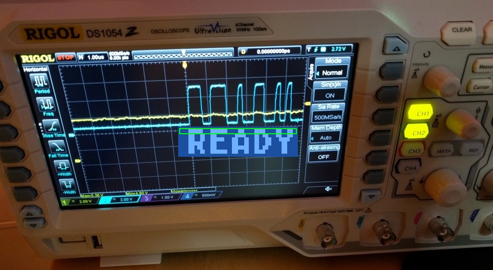
It took me a few moments to figure out that what I'm actually seeing is the top pixel row of the classic "READY" prompt, but yup, that was it. So it seemed that getting a frame dump shouldn't be a problem.
By the way...
If want to improve your binary file and protocol skills, check out the workshop I'll be running between April and June → Mastering Binary Files and Protocols: The Complete Journey
The next step was to connect the logic analyzer and acquire some samples. The one I have is actually 6.25MHz in case of analog data - this sadly meant that my horizontal resolution won't be good at all, as it leaves below 400 samples per scanline (6.25M / 25 FPS / 625 lines == ~400). Still, I figured it will be enough to see if there are any artifacts in the frame at this point.
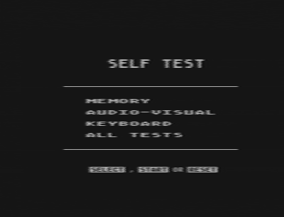
A single frame in Saleae Logic looked like this (this was taken when Atari's Self Test was on):
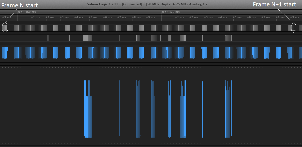
I've exported the data to a nice 400MB CSV file and written the following Python script to convert it into a series of grayscale raw bitmaps (each CSV file contained about 50 frames):
import sys

def resize(arr, sz):
  fsz = float(sz)
  arr_sz = len(arr)
  arr_fsz = float(arr_sz)
  k = arr_fsz / fsz
  out_arr = []
  for i in range(sz):
    idx = int(i * k)
    if idx >= arr_sz:
      idx = arr_sz - 1
    out_arr.append(arr[idx])
  return out_arr

def scanline_to_grayscale(scanline):
  MAX_V = 7.0
  scanline = resize(scanline, 400)
  scanline = map(lambda x: chr(int((x / MAX_V) * 255)), scanline)
  return ''.join(scanline)

if len(sys.argv) != 2:
  print "usage: process.py <fname.csv>"
  sys.exit(1)

f = open(sys.argv[1], "r")

# Ignore headers
f.readline()

CLOCK_BOUNDARY_V = 4.7
FRAME_BOUNDARY_COUNT = 100  # Actually it's ~21 vs ~365. 100 is an OK value.

scanline = None
clock_high = None

ST_INIT = 0
ST_LOW = 1
ST_HIGH = 2

state = ST_INIT
frame_sync = 0
frame = -1

fout = None

for ln in f:
  ln = ln.split(', ')
  t, clock, composite = map(lambda x: float(x), ln[:3])

  clock_high = (clock > CLOCK_BOUNDARY_V)

  if state == ST_INIT:
    if clock_high:
      continue
    state = ST_LOW

  if state == ST_LOW and clock_high:
    state = ST_HIGH
    scanline = []

  if state == ST_HIGH and clock_high:
    scanline.append(composite)
    continue

  if state == ST_HIGH and not clock_high:
    state = ST_LOW

    if len(scanline) < FRAME_BOUNDARY_COUNT:
      frame_sync += 1

      if frame_sync == 3:
        frame_sync = 0
        frame += 1
        print "Dumping frame %i..." % frame
        fout = open("frame_%.i.raw" % frame, "wb")
      else:
        if fout is not None:
          fout.close()
          fout = None
    elif fout is not None:
      fout.write(scanline_to_grayscale(scanline))
The script generated about 50 frames for a dump of "READY" screen and a similar amount for "Self Test" one. All the frames looked more or less like this:
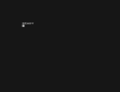
So, apart from the low resolution and lack of color (both expected) they actually did look correct.
Which means that the GTIA I have is probably OK. One thing to be noted is that my script actually had access to the composite sync clock and the TV tuner doesn't - so if the timing slightly off my script would not catch it.
Nevertheless it was a pretty fun exercise. The next thing on my list is to read more about Composite Video and verify that all the timings at GTIA output, and later on the Composite Video cable, are actually OK. Once I do that, I have to learn analyze the circuitry that lies between the GTIA and the monitor output socket, check if all the paths look good, etc. Should be fun :)
And that's all in today's noob's notes on ECs and old computers. Stay tuned!
P.S. Please note that there are probably several errors in this post - as mentioned, I don't know too much about this field, so errors/misconceptions/misunderstandings are bound to occur. There might be some updates to this post later on.
Comments:
Are you sure Atari generates video signal that is compatible with standard? Some of old game consoles abuse video signal and generate strange formats like PAL in 60 Hz, or Apple 2 where color generation is very hackish.
It would be helpful to attach your Atari to normal analog TV. From video it looks like there's a problem with sync, I suggest looking there. Also it is possible that your oscilloscope supports CVBS video decoding or at least syncing to it.
This guy is using oscilloscope to capture raw video and then process it in Octave to get image - kinda cool:
https://www.youtube.com/watch?v=SWVu-qPR-Ws
..but honestly... - you are single, have no friends (apart from those online), you are a virgin, you have too much time on your hands... you are a socially unskilled and terrified of talking to strangers, you never go out... YOU ARE A TOTAL WEIRDO.
Well done with your Atari though :)
Yeah, me too ;)
If I'm ever skilled enough I'll make one though.
@jaczekanski
Thanks! I'll investigate :)
As for the oscilloscope video - yup, saw it - it's epic :)
@lol76
Hey! Online friends are real friends!!!one ;)
so please break every device in your house and fix it and don't forget to make video
Haha :) I agree, but my wife read this comment and asked not to break everything in our house.
I could always get a second pair of whatnots I guess...
Still a lot of learning ahead of me before I would be able to analyze the simplest of things.
@AndyB
Thanks!
Add a comment: